Detailed piping company name drawn checked date drawing no. Concentrations of fuel oxygen and inert material are plotted on the three axes.

Gas Piping Part 2
1 Btu per hour 0293 W Maximum gas demand of outlet A 31 CFH 35000 btuhr divided by 1100 btu per cubic foot.
. Using tables IV V or VI in Questars Good Practices for Gas. We can focus on the regions separated by the lines in these diagrams and get some idea of the conditions of temperature and pressure that are most likely to produce a gas a liquid or a solid. If you want to add another line just move the mouse to the 2nd point of this new line and click.
Determine the work done by the gas on the cylinder and sketch a PV diagram of the situation. These can be found from the phase diagram by drawing a line across at 1 atmosphere pressure. The solid-liquid equilibrium line the melting point line slopes backwards rather than forwards.
Creating gas line diagram. Our reports are professional and detailed. Ive started this by running 34 pipe but when I try to connect the.
How To Draw Riser Diagram - Not Too Easy Sorry. These diagrams indicate the physical states that exist under specific conditions of pressure and temperature and also provide the pressure dependence of the phase-transition temperatures. Last time we just did a dummy one with detail lines but Im wondering if its worth it to make one by actually modeling the pipes in the wall.
Youve seen the diagrams and feel you can draw the lines and magic happens. Your line is drawn. Open and save your projects and export to Image or PDF.
Move the mouse to the 2nd point of the line and click. To move a line. Electron orbital diagrams and written configurations tell you which orbitals are filled and which are partially filled for any atom.
Use our diagram editor to make Flowcharts UML diagrams ER diagrams Network Diagrams Mockups floorplans and many more. The gas mixture represented by AC on line AB is too lean to catch fire while DB is too rich mixture to get fire. Rated input908 BTUCFH A- 3000090833 Cubic Feet per Hour CFH B- 2500090828 CFH C- 7500090883 CFH D- 136000908150 CFH Total Demand294 CFH LONGEST LENGTHRUN Meter to Water Heater is 60 feet.
The phase diagram for water. A piping and instrumentation diagram is drawn up at the design stage of a process to model the system. A general way to represent the flammability of a gas or vapor is by a triangle diagram shown below.
It explains how to calculate the work done by a gas for an isobaric process iso. We can also focus on the lines that divide the diagram into states which represent the combinations of. During an isobaric process the gas is heated and expands from 025 m3 to 055 m3.
Free editor to create online diagrams. When interpreting a single line diagram you should always start at the top where the highest voltage is and work your way down to the lowest voltage. TXLs should be j013724 my correction Figure 5 Single line reactance circuit diagram reactances shown on a per-unit basis 7.
Calculate Operating Conditions of the Motors If the motors are operating at 12 kV this represents 12 kV138 kV 087 per-unit. Gas fireplace direct vent 40000 36 Gas log unit 80000 73 Barbecue 40000 36 Gas Refrigerator 3000 2 For SI units. Lehi City - Lehi City.
The number of valence electrons impacts on their chemical properties and the specific ordering and properties of the orbitals are important in physics so many students have to get to grips with the basics. It consists of a combination of the process flow datasheet the mechanical equipment design and the instrumentation engineering design. You want to know how to draw a riser diagram.
Diagrams can range in complexity and either be hand-drawn or created using specialty software. If you dont want to add another line just right-click. Electrical Diagrams Our electrical diagrams conform to national codes and are done professionally in Autocad.
The single line diagram of a power system is networked show the main connections and arrangement of the system components along with their data such as output rating voltage resistance and reactance etc. To get started we need a floor plan showing all the gas appliances along with BTU per appliance. The air line in the figure represents all possible combinations of fuel plus air.
A phase diagram combines plots of pressure versus temperature for the liquid-gas solid-liquid and solid-gas phase-transition equilibria of a substance. Each apex of the triangle represents either 100 fuel oxygen or nitrogen. W - PΔV W - P Vf Vi W - 40e5 055 025 W -12e5 J The PV diagram shows a gas going from a.
A gas at 40e5 Pa is in a cylinder with a piston. Example Gas Line Schematic SOLUTION AND EXAMPLE. Now according to the diagram When we go left to the line AB Add inert gas to the tanks there is a sudden change in tank atmosphere.
LIST OF COMPONENTS A - GAUGE COCK F - PLUG B - MOTORIZED VALVE G - EXPANSION JOINT C - R025 FLANGED ELBOW H - ECCENTRIC REDUCER D - PRESSURE READOUT I - TURBINE E - LOCKED VALVE INLET STATION MAIN BUILDING A B FRESH AIR INLET 50 Exterior Pipeline LO GAS IN 600 Series. GAS Plumbing Riser Diagrams If you need a gas riser diagram let us prepare it for you. Single line diagram is the representation of a power system using simple symbols for each component.
Industrial single line diagram. I am being asked to create a gas line diagram for a residential house that shows btushr of appliances. When you release the button the grey line will be displayed again and will follow the mouse.
There is only one difference between this and the phase diagram that weve looked at up to now. Now lets go through a industrial single line diagram. Draw the Reactance Diagram The completed reactance diagram is shown in Figure 5.
CLICK HERE if you want me to draw a riser diagram for you. This physics video tutorial provides a basic introduction into PV diagrams. Sionoftheformonthisdiagramoftheexpansionlineforwet steam flowing through amultistageturbineof known stage effi- ciency and the development of apractical method for.
Ad Templates Tools Symbols To Make Easy Business Diagrams. Phase diagrams can be used in several ways. You need to pull your permit and youre stuck.

A Diagram Of A Mass Flow Controlled Gas Line L 1 Download Scientific Diagram
2

Schematic Diagram Of The Lpg Pipeline Supply Mode Download Scientific Diagram

M E P Drawing For Gas Layout 2d Auto Cad Of Uae In Building Line Sample Youtube
2

Gas Diagram Drawings
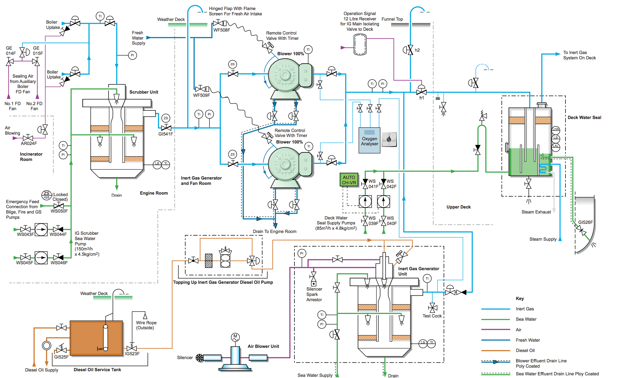
How To Draw And Read Line Diagrams Onboard Ships
Installing Gas Piping King County
0 comments
Post a Comment